View the list of specifications. See Listing Specifications. From the listing check one specification.
Select Actions > Content Report
> System Document.
The System Document option is not available for users having the Employee
role.
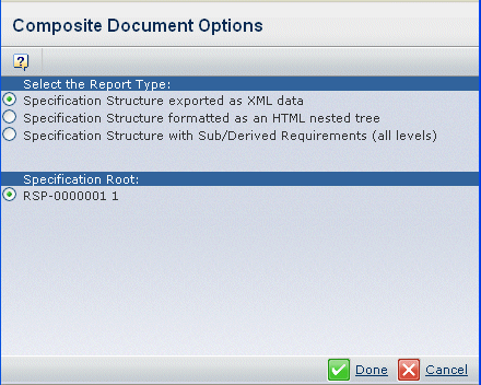
The Composite Document Options page opens.

In the example above, this is how the root objects mapped:
- Fn Root 1 implements Spec A, Log Root 1 implements Spec A, Log Root
1 implements Fn Root 1 (which gives row #1, #2, #6).
- Fn Root 2 implements Spec A (which gives row #3).
- Fn Root 3 implements Spec A, and Log Root 3 implements Fn Root 3
(which gives row #4, #5).
From the Select the Report Type listing, select
the query.
- Function/Logical Structure Export (XML) with Ports and Flows
System document with functional information and logical representations,
including sub-flows and sub-types, from VPM RFLP. This is rendered in
plain XML.
- Function/Logical System Document (HTML) with Ports and Flows
System document with functional information and logical representations,
including sub-flows and sub-types, from VPM RFLP. This is rendered in
HTML.
From the Function Root, select an option.
Following are details about the different root context options:
- Row 1. You can choose to generate the system
document with requirements, function and logical details. Displays the
Fn Root 1 and Log Root 1 context combination to take into account the
implement links between the Spec A < Fn Root 1, Spec A < Log Root
1 and Fn Root 1 < Log Root 1.
- Row 2. You can choose to only generate a document
with requirements and function details. Displays the Fn Root 1 only and
takes into account only the implement links between the Spec A < Fn
Root 1.
- Row 3. Displays the Fn Root 2 only and takes
into account only the implement links between the Spec A < Fn Root
2.
- Row 4. Displays the Fn Root 3 and Log Root
3 which takes into account the implement links between the Spec A <
Fn Root 3 and Fn Roo3 <Log Root 3.
- Row 5. Displays the Fn Root 3 only and takes
into account only the implement links between the Spec A < Fn Root
3.
- Row 6. You can choose to only generate a document
with requirements and logical component details. Displays the Log Root
1 only and takes into account only the implement links between the Spec
A < Log Root 1.
Click Done.
The report generates the complete XML or HTML of the System Document.
|