Saving Designs to ENOVIA | |||
| |||
Click ENOVIA > Save > Active or All from the SolidEdge toolbar.
- Active: Click to save new or modified designs that are active in the current session of SolidEdge.
- All: Click to save all new or modified designs which are loaded in SolidEdge.
Warning: An error message is displayed and ENOVIA Save dialog box does not open if there are no changes to be saved in the designs open in SolidEdge. 
All the designs open in SolidEdge that are new or modified are listed in the ENOVIA Save dialog box. For each design, the ENOVIA Save dialog box lists,
Note: Component OLE attachments are also displayed along with the modified component in the Save dialog box.
Warning: Drawing file is modified after switching windows and activating it back. The Status column in ENOVIA Save dialog box displays the status as Modified for such designs. This is a known limitation. - A selection check box is available for the designs displayed in the ENOVIA Save dialog box. Select the check box corresponding to the required designs to select the designs for save. Designs corresponding to unselected check boxes are not considered for save.
Note: The checkboxes are preselected for the modified (including Locked by self, un-locked, type-changed) and new designs.
- An alert
 is displayed for the designs corresponding to the check boxes that cannot be selected for save. For example, is displayed for designs that is locked by another user, in Release state, or obsolete. The check boxes corresponding to are grayed out and cannot be selected. Point to to view the tool tip. The tool tip displays the reason why the design cannot be selected for save.
 -
 . Displays the lock status of the design in ENOVIA. icon is displayed if the design is locked by you or any other user.
  icon is displayed if the design is not locked in ENOVIA. For a new design, no icon is displayed.
 - Name. Name of the design.
 . This icon is displayed for designs that are saved to ENOVIA Workspace. Roll-over mouse to view the name of the workspace where the design is saved. For a new design, this is blank.
- Type. The type of the design.
- Rev. Current revision of the sequence. This is blank for a new design.
- Status. Status of the design in ENOVIA. One of the following status is displayed for each design:
- New. Displayed if the design does not exist in ENOVIA.
- Modified. Displayed if the design is modified in SolidEdge since the design was last saved or opened.
Note: Drawing files are modified after switching windows and activating it back. The Status column in ENOVIA Save dialog box displays the status as Modified for such designs. This is a known limitation.
- Obsolete. Displayed if newer version of the design exists in ENOVIA database.
- State. Current maturity level of the design in ENOVIA lifecycle. This is blank for a new design.
- Locked By. If the SolidEdge design being saved already exists in ENOVIA, and is locked by any user, then this column indicates the name of this user. In the case of saving a new design, this column is blank.
- Description. Description entered for the design by the user.
- CAD Attributes: This column is displayed only if Show CAD Attributes check box is selected. See
You can enter the following details for saving the design.
 . Click to select all the new and modified designs from the listed designs.
- Save To. The ENOVIA workspace where the designs will be saved. For selecting a workspace, see Saving Designs to ENOVIA
- Comments. Enter comments for design you are saving. The comments are stored as an attribute in the design in ENOVIA.
- View. Click and select a table defined by the Integration Administrator from the drop down list. The selected table is applied to the ENOVIA Save dialog box.
Note: For details on behavior changes in Save feature when read-only option is selected, see About Saving in ENOVIA.
Set Save Options
This section shows you how to set options for Save.
Click Options to open the ENOVIA Save options dialog box.
Note: To support your business processes, your Integration Administrator may have defined some options so they cannot be changed. If the options are modified during a save operation, these parameters will return to their default setting during the next save operation. To permenantly change these settings, it must be set using the Design Central web user interface. See "Setting Global Preferences" section in ENOVIA Designer Central Installation and Administrator's Guide for details on setting these preferences using ENOVIA Designer Central. Select the options to be executed when you save selected designs to ENOVIA.
![]()
Select a Workspace to Save Designs
This section shows you how to select a workspace to save designs.
![]()
Use Autoname
The Autoname option is available depending on the Preferences set by the Integration Administrator. Only designs with status "New" can be named using Autoname.
The Autoname series for each type must be set in the ENOVIA Save options dialog box.
- In the ENOVIA Save dialog box, right-click designs with status "New" and
click Autoname.
The naming is done for the selected designs as per the autoname series set for each type (CAD Model / CAD Drawing) in the Save Options dialog box and the auto-names are displayed under the Autoname column in ENOVIA Save dialog box.
Note: Auto name series created for types “CAD Drawing” and “CAD Models” are supported. If object generator is created for types (SE Drawing, SE Assembly etc) derived from the mentioned base types in Matrix navigator, then such auto name series created for integration specific types will not be shown in integration UI.
Note: Auto name for assembly family type objects is not allowed. This is a known limitation.
![]()
Set Derived Outputs
You can set specific type of derived output for each particular design type for the current save session using the Save Options dialog box.
Click Derived Outputs in the Save Options dialog box to open the ENOVIA Derived Output Options dialog box.
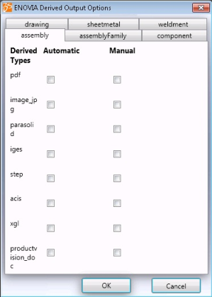
The tabs in the ENOVIA Derived Output Options dialog box correspond to the CAD types mapped by your Administrator in the GCO.
Note: The derived outputs options which are selected by default or are enforced in the ENOVIA Derived Output Options dialog box are read from your preference settings done in the web user interface, when you log in to ENOVIA using the immersive UI.
Warning: The Derived Outputs option is not displayed if the Administrator has not defined any mappings in your GCO.
![]()
Revise Designs
The Revise option is available upon right-click on new and modified designs in the ENOVIA Save dialog box. Ensure that the revision sequence is set in the ENOVIA Save Options dialog box.
Right-click the selected designs and select Revise.
A new column, Target Revision is added in the ENOVIA Save dialog box.
The target revision specified in the ENOVIA Save Options dialog box is set as the revision.Note: You can edit the values of the revision specified under the Target Revision column.
Note:
- You can enter any existing (stored in ENOVIA) or new revision in Target Revision column.
- It is not mandatory that the subsequent revisions specified are in sequence. For example, the specified revisions can be of the order, A, B, and F.
- Once a higher revision label is assigned, then you can assign only an existing earlier revision to the designs. For example, if the existing revisions are A, B, and F, then the next available revision is 'G'. The revisions C, D, and E cannot be used. The existing revisions, A,B, and F can be reused.
![]()
Revise All Designs
The Revise All option allows you to revise new and modified designs from the ENOVIA Save dialog box which are revisionable, in a single go.
![]()
View Attributes of a Design
You can view the attributes of a design from the CAD Attributes column in the ENOVIA Save dialog box. You can also view the attributes of a design using the CAD Attributes dialog box even for designs that cannot be selected in the Save dialog box.
Click Show for any design in CAD Attributes column to view the CAD Attributes dialog box.
You can also open the CAD Attributes dialog box for designs that cannot be selected in the Save dialog box.
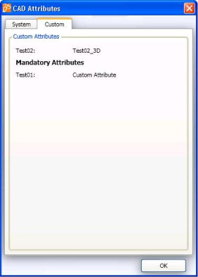
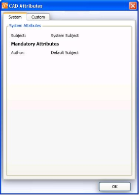
The CAD Attributes dialog box displays the following attributes specified for the design in the System or the Custom tab:
- Normal Attributes: Attributes that are not mandatory are displayed.
- Mandatory Attributes: mandatory, default, and null attributes that are mapped in the GCO by the Administrator are displayed in the System or Custom tab. If the attribute is mapped as mandatory, then the values entered in the GCO are displayed. If the attribute is mapped as default, then the value specified by you is displayed. If values are not specified by you, then the value specified in the GCO is displayed. If the attribute is mapped as null, then the value specified by you is displayed.
Attributes that are Solid Edge specific but not system attributes are displayed under the Custom tab.
Mandatory attributes are displayed in the Mandatory area in System and Custom tabs.Notes:
- The tabs displayed in the CAD Attributes dialog box depend on the attribute mappings. Tabs are not displayed for types that are not mapped.
- The attributes displayed in the CAD Attributes dialog box cannot be edited.
- An error message is displayed if the attributes are not mapped for the design.
- The attributes for ENOVIA custom Type or OOTB type are displayed in the Save dialog box if some custom types are present in ENOVIA for some CAD types and are also added to the GCO by your administrator. In case a certain attribute is mapped only for OOTB type in the GCO and the object being Saved to ENOVIA is of custom type, then this particular attribute is not displayed in the Save dialog box.